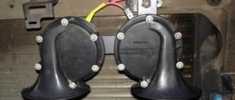
Finally, everything was won, the wiring was stretched and everything was connected! The goal was to lengthen the wires of the power window buttons and connect them to the ESP unit from Kalina, connect the central locking and illuminate the mirror joystick (I don’t have electric mirrors). During the work, I came across a Falcon WR-400 glass closer, it has 4 glasses, but for now they installed two, with a reserve for the future)) And so, everything in order:
Connecting power window buttons.
I hope the author won’t mind, I took this blog entry as a basis, as well as several others.
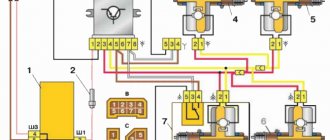
Pinout for connecting power window buttons.
1) +12V for the driver's window (Window moves down) 2) +12V for the driver's window (Window moves up) 3) Ground 4) +12V for the driver's window 5) Ground 6) +12V for the passenger's window 7) None Dimensions 9) +12V for passenger window (Window moves down) 10) +12V for passenger window (Window moves up)
Accordingly, I extended all the wires and attached small terminals at the end, because... I couldn’t find the connector (oh, that is, I didn’t look...) Also, wires from a Falcon WR-400 were embedded into these wires. I can’t tell you about connecting it, our installer volunteered to help me and did everything himself)) But I think there won’t be any problems there! I know for sure that they pulled one wire from the alarm unit and another wire pulled the positive one, so that without the ignition the unit could raise the windows.
Connecting the central lock button
I also can’t tell you exactly where the two wires came from that are responsible for opening and closing the doors if you apply ground to them. But I assume they come from the central locking unit that was installed at the factory. On my car it is located at the driver’s left foot, a little higher under the dashboard.
Pinout for central locking connection. 1 closing 2 ground 3 missing 4 dimensions 5 backlight ground 6 missing 7 opening
We also connected all this, and also ran the wires for the joystick backlight:
2 dimensions 5 weight dimensions
Well, as I said, I messed around with the hard door trim until I solved the problem and installed it as is. Here's what the bundle turned out to be:
All that remains is to pass the successful testing stage and I am satisfied!)
Installing an additional ESP button in the door of a VAZ 2110, 2111, 2112 and operating the ESP without ignition and relay
The content of the article:
ESP operation without ignition and relay for VAZ 2110, 2111, 2112
As we all know, the Internet is full of information on how to wind a wire and make the power windows work without the ignition key, but it seems to me complete nonsense. Let's look into this.
The proposed method on the Internet is this: first of all, we must open our mounting block with fuses and find there the relay responsible for the electric windows.
Having verified it experimentally, namely by turning on the ignition and pulling out the relay, we understand whether the window lifts work or not. If this is what we need, take out the relay.
Then we begin to do some manipulations with the relay by winding wire around it.
I don’t know about you, but I have a question: why do we need this?
We have in our hands an ordinary 4-pin relay, where the principle of operation of the relay is clear to us.
On the Internet they simply suggest that we short-circuit the water contact of the power supply-30 and the output contact of the ESP-87. This will lead to a contact that bypasses the coil (relay), which will only work if it receives power (plus) from the ignition switch (contacts in Relay-85,86-Coil).
So isn’t it easier for us, without making a collective farm, to simply make a jumper to provide power directly?
Make it from a thick wire with a cross-section of 2.5-4 squares so that our jumper does not get hot.
And connect it directly to the block. On the input voltage connector, contact is 30 and output voltage is 87.
Then to turn on the ESP you will not need to turn the ignition key. Since Power (plus) will come to the ESP, bypassing the relay, which will only work when power (plus) is supplied from the ignition switch.
Then there will be no need to farm collectively.
Installation of an additional ESP button in the door of a VAZ 2110, 2111, 2112
I bring to your attention a step-by-step description of the process of installing an additional power window control button (ESP) in the door. The process is not very complicated and time-consuming; everything will take about two hours.
In order to install an additional power window key on the VAZ 2110 door, we will need:
1. 9 meters of wire (I used wires of the following colors: black, yellow, white, 3 meters each) 0.75 mm (section) 2. Button for controlling the ESP (VAZ 2110)* 3. Block for the ESP button 4. Terminals "mother" large - 2 ** 5. Terminals "male" large - 2 ** 6. Terminals "mom" small - 7 ** 7. Terminal "ground" 8mm - 1 8. Blocks for terminals "mother - father" large — 1 (of each type) 9. Plastic clamps (small) — 8 10. Pistons for sprinkling the door trim — 7***
* - in principle, instead of a ten-point rocker button, you can install HIGH-CURRENT (power) buttons from Kalina or Priora, but check with the seller that they are high-current, trigger ones will not work. ** — I didn’t buy these terminals, they came with the pads. *** - they are soft for me, so they didn’t break => I didn’t buy them.
Wiring diagram for the ESP button in the door.
Now we determine the contact numbers on the button and block, according to the diagram:
Okay, we figured it out. The next thing is to find the ESP relay. Typically, the relay is located on top of the mounting block cover. If you have more than one relay installed, then remove them one by one and check if the ESPs are working. The relay, after removing which the ESP stopped working, is the ESP relay.
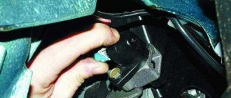
We remove it from the socket and remove the negative terminal from the battery. Then we disconnect the relay itself from the housing. To do this, use a flat-head screwdriver to slightly press the holder latch and press on its body. The relay holder will disengage. The picture shows the latch:
We are interested in the white wire with a black stripe (this is “+ 12 V” after ignition. If you want the ESP to work regardless of the position of the ignition key, then bridge contacts 30 and 87 of the ESP relay - white with a black stripe and blue with a black stripe) :
We connect our “+12 V” wire to it (according to the diagram, it is connected to pin 2 of the block, I used a yellow wire) Now we need “ground”. You can take it from the door, but the contact there is very unstable, so I took the mass from the bolt behind the mounting block. To see this bolt, open the mounting block and look up and slightly to the right).
Crimp the wire that goes to ground at the ground end and attach it to the bolt. (I used black wire for these purposes)
The next step is to connect the plus from the backlight. I ran into the white wire of the ashtray illumination (I also used a purchased white wire for connection), it is located behind the shield on the left, at the feet of the front passenger.
Do not pay attention to the orange wire (+ to the radio backlight).
Now, we have connected all three wires that we will run into the door to the sources, then we will need to run them through the corrugation inside the door. Remove the center pillar trim (unscrew one screw in the middle and two at the bottom). Also loosen the fastening of the driver's seat belt on the floor (bolt 17).
To make it easier to route the wires through the corrugation, disconnect it from the door.
Unscrew and remove the door handle (two bolts for a Phillips screwdriver). Then we remove the door trim (card), it is best to do this starting from the bottom. Don't forget to unscrew the nail. We find the blocks (male and female) for the ESP engine and disconnect them.
Now the fun begins. We crimp the three wires we have drawn with little mothers and insert them into the block according to the diagram given above. Accordingly, “+12 V” - (yellow) contact 2
, plus backlight (white wire) -
4
, and ground - black - by
5
.
There are 4 contacts left: 1,3,6,7. We connect the original wire (green with a black stripe) that went to the ESP engine block to 6
, and the orange wire to
3
.
Now the block that will be connected to the ESP engine block: blue wire - 7
, brown -
1
contact.
Here, in fact, is the photo (all numbers and designations are in accordance with the diagram above):
Location of wires in the block:
I tidied this mess up a bit:
We connect the button, connect the ESP relay and the minus to the battery. Let's check... if everything works, put all the parts in the reverse order of disassembly. If the glass works normally with the native ESP buttons, but with the connected ones it goes in the opposite direction, swap 3-6, and 7-1 (was 3 - became 6, was 6 - became 3, etc.) contacts in pads that connect to the original wiring in the door. But first, check that the connection according to the diagram is correct.
Technical characteristics of the AMP HD DVR-600 video recorder, installation and correct connection of the video recorder in VAZ 2110, 2111, 2112 via a toggle switch
Contents of the article: 1. Technical characteristics of the AMP HD DVR-600 video recorder for VAZ 2110, 2111, 2112 2. Installation of video
Alexmtx › Blog › Correct connection diagrams for electric windows (ESP) and glass closers
When you need to install ESP (electric windows) yourself, then, as always, on the Internet it is difficult to find correct and understandable diagrams for everyone. Having experience in radio electronics, I am laying out for everyone the correct and understandable diagrams for connecting an ESP, an intelligent glass closer Pandora DWM-210 (but it is better to install a Sheriff PWM-200), as well as simple closers only for raising the glass, installed in the wire gap on the positive side of the motor.
We take ESP power keys (not trigger (multiplex) from Itelm): a block from Granta, and a new model button from Kalina (it is the power key), since they are the cutest in appearance.
These are, of course, not dual-mode imported buttons, but they will work just as well with an intelligent door closer. We also install the Sheriff PWM-200 type door closer itself. We use thick power wires (shown in bold in the diagrams) >= 1 mm2, while control wires can be used thin = 0.5 mm2.
Power buttons are easy to identify by their contacts - they have thick and flat blades, while trigger buttons have thin pins like needles! Exception! If the buttons are not on the door, but on the center console and thick wires >= 1.5 mm2 are stretched from them to each door, then you can do without a relay, since there is no duplicate button here, and each one has its own door and the drawdowns are minimal. Then you don't have to read further.
Plus +12V must be taken from the fuse block, and not from the ignition, otherwise the automatic window closer will not work when arming. It is better to take the weight from the bolt behind the mounting block, and not in the door, since the contact in the door may not be very good. Although the door contact is also good if the car is not old. Take tinned terminals.
Connection diagram for power window lifter button "AVAR"
Diagrams for connecting the backup button on the driver's door to the main button on the passenger door
When installing two buttons on one window regulator, they are usually installed in series (or in parallel, but then they must be decoupled via a relay).
The main button is the button that controls the power window of the door on which it is installed. The duplicate button is the driver's button, which additionally controls another window regulator from the driver's seat.
Daisy chain connection (for trigger buttons)
We connect the output of additional button 1 in the driver's door to input 6, and output 7 to input 3 of the main button on the passenger door. We cut the wires in the block connecting contacts 5-6 and 6-3. The minus of contact 5 now goes only to the backlight, and contacts 6 and 3 now take output from additional buttons 1 and 7 of the driver's door. Installation in parallel will result in short-circuiting during lifting and lowering. Power wires are highlighted in bold.
Parallel connection (only for power buttons)
Since with a serial connection you still can’t do without a relay, it is better to make a button duplication circuit in parallel, decoupling the main button from the backup button through two 5-pin relays: the wires from the main button next to the driver’s ESP motor go directly to the 88th contact of the relay and from pin 30 directly to the engine, and long wires from the backup button go to pin 85 of the relay winding, and the relay feeds a powerful plus to the passenger’s ESP engine.
A parallel connection for power buttons is preferable, since there is no need for a relay on the main (passenger) button (the wires here are short), and we thereby eliminate unnecessary clicking of the relay when the main button on the passenger door operates. For non-power (trigger) buttons, in this case, you will definitely have to use 2 more extra relays to relieve the load on the passenger button (therefore, a serial connection is always used for trigger buttons). Further, everywhere in my circuits a parallel connection is used, since all the buttons are power
.
Connection diagram for multiplex (low-current) ESP button
ESP connection diagram when the multiplex button closes the contacts to ground
Dimensions of the installation location for the ESP “AVAR” buttons
Glass closer Pandora DWM-210
What it gives: - full glass travel in one short press (“one touch”) - BUT DOES NOT WORK ON 2 GLASSES AT THE SAME TIME (since the module has only one sensor for electromagnetic noise of the motor, current and time); — stopping the glass in any position by pressing again in any direction; — automatic stop of the glass when it encounters an obstacle in the window opening; — automatic shutdown of ESP motors when current is exceeded; — automatic closing of windows when arming the car; — automatic opening of the windows when disarming to the previous position before arming, if the parking lasted no more than 20 minutes. (The rev counter works rather conditionally and may leave the windows closed or not closed enough). The closer is installed in the driver's door.
ATTENTION! When you hold the button, the closer does not use its relays
, which take the plus (through a 20A fuse) and minus from the closer, but sends all the current directly from the button to the motor, so you need to install a relay after leaving the button with long wires!
Apparently this was done so that if the door closer fails, you can always close the window by simply holding the button. When you briefly press
the button, the door closer with its relays is activated and closes the glass.
Place the relay only at the input to the closer from the output after the duplicate button!
If this is not done, then due to subsidence along the long wires of the sequential connection of the buttons, the passenger window will barely move.
The output of the closer must be connected directly to the motor without a relay, otherwise the detection of electromagnetic noise from the motor will not work and the closer will not work!
At the output of the driver's power button, relays are not needed, since all the power wires there are short.
It is ideal to install 2 door closers on each door, as is standard on foreign cars - then the AUTO mode will be on 2 doors at once in parallel, and not alternately. In addition, you will not need to pull 2 extra thick wires to the motor from the driver's door to the passenger's door. If I had known right away that the Pandora DWM-210 is such a Ketai crap without its own relays in the power part of the closer, I would have purchased and installed a Sheriff PWM-200
, in which the power part is clearly separated from the control part and, moreover, you can close two windows at the same time in one touch! So it's definitely better!
This is interesting: What to do if the “CHECK” lights up?
The power windows are turned on by the module sequentially after a trigger pulse is given: first the driver's door, then the passenger door, and the next channel is turned on after the previous one has been completed. If the glass is already closed, the module will immediately switch to the next channel. Closing control is carried out by electromagnetic noise from the motor.
When the power is turned on, the closer module needs to be calibrated based on the protection current. You need to press SHORTLY to lower each glass all the way, then raise it in the same way. At the same time, the closer remembers the characteristics of the engine. The control signal for closing and opening is NEGATIVE ONLY. Control can be done from the central locking or from an additional alarm channel. It is necessary to connect the control output of the security system to the “White/Red” (windows up) and “White” (windows down) terminals of the module, respectively. The duration of the trigger pulse must be at least 500ms. (0.5 sec.). Attention: in older releases the wires of the buttons and motors were swapped - for such blocks we swap the wires under the numbers: 9 2, 16 20, 15 10, 14 19, 13 18. On the latest Pandora (November 2011 and newer) the diagram is correct, so that there is no need to swap wires from buttons and motors!
Closer in wire break for lifting ESP
Addition dated 10/05/2014 at the request of SIBUR95. There are closers that are connected to the break in the lifting wire that goes to the ESP motor. There are 2 wires coming from the closer and they are constantly closed in it. When you turn on the closer, they break and + appears on one, and nothing on the second. On GREEN, when the door closer is operating (arming), a plus appears and it goes to the engine, and a minus goes from the button (or from the relay from contact 88 to 30) to the engine. When the closer does not work, it simply passes current from BLUE to GREEN by closing its relay and that’s it.
Here the circuit differs only in that the minus of the motor is connected directly to the button (or to the relay, if the button is duplicated), and the plus also passes through the closer, and the relay is located at only one input to the closer, thereby not interfering with the detection of engine noise.
You can also make a button duplication circuit not in series, but in parallel on two 5-pin relays. The advantage is that a series circuit is eliminated; the relay will not click again from the main button, which is closer to the engine (with short wires), but only from the backup one. The downside is that for non-power (trigger) buttons in this case you will have to use 2 extra relays (relays 3 and 4 in the diagram).
Scheme for any number of duplicate buttons and number of doors
You can put as many buttons in parallel as you like and simultaneously press them in different directions - a short circuit is impossible from the circuit design! In a situation where we press the up button on the main button, and the down button on the backup button, it will simply stop, since both power lines will have the same potential.
The only difference between the closer is the presence of an MK between the buttons and power relays. The advantage of the circuit is that the power switching is in one place, there are no losses in the harnesses and on the buttons, there is a minimum of “pulling” of wires - 2 in total per channel + ground. In good quality, full-featured closers, the power part and control lines are implemented in the same way + the functions of “auto-detection” of active control levels are also added.
If a door closer of the PWM-200 on Sheriff type with low-current control is installed, then there is no point in these relays, since they are already mounted in the door closer. This circuit with a relay is for understanding the essence of reverse control and duplicating buttons in parallel. Power outputs both in the central locking system and in the door closers are implemented in exactly this way.
It is also advisable to connect non-polar electrolytic capacitors of 22 uF 25V to the contacts of the ESP motors in order to smooth out the range of current ripples in the power channel of the closer so that it works correctly even when the motors are worn out and does not suddenly stop the glass when opening and closing.
The usual scheme of duplicate buttons for 4 doors
Duplicate buttons must also be supplemented with two 5-pin relays (they are not shown in the diagram).
The device of the VAZ window regulator of the tenth model
The design of the window lifters on the VAZ 2110 will be different depending on whether the device is for the front or rear doors.
But despite this, each of them has certain details in its structure:
- Grooves that are located on the inner plane of the door frame. These components are designed to hold the glass directly in one position or another.
- The so-called rails. These components are mounted in the door body. They are used as guide components for moving glass.
- Directly sealing element made of soft rubber, which allows you to limit the movement of glass in the up and down directions.
- Lifting device.
- Window lift drive.
Installation process of electric windows
In addition, it is necessary to install the power windows themselves. The procedure is performed in the following sequence:
- temporarily remove the glass seal located on the inside of the door;
- remove the glass, and then dismantle the window regulator fastening mechanism;
- we install devices that will operate from an electric drive;
- connect the negative terminal to the battery and check the operation of the new window regulator;
- We install the glass in place and trim the door.
Repair
It is not possible to repair window regulators in all cases. Mostly, these glass lifting devices can be repaired in case of obvious mechanical fractures of the elements.
But we can still give some useful tips regarding restoring the functionality of the window regulator without replacing it.
- If the electric window motor fails to work, then the brushes or winding are most likely to blame. To verify this and fix the damage, you need to remove the motor, disassemble it and clean the outer and inner surfaces.
- For cleaning, it is recommended to use a lint-free cloth. The cloth is soaked in gasoline, alcohol or a special cleaning agent. When you buy the latter, you can use it for a long time, the efficiency is higher compared to gasoline.
- After cleaning and drying the parts, it is recommended to treat the moving elements with lubricant so that the mechanisms function longer.
- If the cable comes off the lifting mechanism, you will have to dismantle it, remove the electric motor, or unwind the cable if it is mechanical. Then the cable is pulled back onto the grooves and the assembly is reassembled.
- If a malfunction occurs in the mechanism or the electrical circuit of the device, it is necessary to study this circuit, determine the direction of the wires, and then ring them. This is the most effective way to check for electrical failure.
Lifting device diagram
Repair in most cases gives only a temporary result, so soon you will still have to make a full replacement. This is due to the fact that each part has its own service life and degree of wear. When they are reached, the window regulator stops working.
Replacing or repairing mechanical or electrical window regulators cannot be called complex undertakings. It is quite possible to cope with such tasks with your own hands.
Let's sum it up
As you can see, installing and connecting power windows, as well as power window buttons, is not the easiest procedure to install, but it is quite possible to do all the work yourself in an ordinary garage.
The main thing is to choose the right window regulator (and, if necessary, a window closer), and the diagram of the window regulators should be studied in advance in order to avoid errors when connecting.
We also recommend reading the article on how to connect a subwoofer in a car. From this article you will learn about the available ways to connect a subwoofer to a radio, as well as what subtleties and nuances you should pay attention to.
Finally, we note that there are a large number of different window lift mechanisms, blocks, buttons, etc. on the market. In practice, it is recommended to buy complete and ready-made kits from trusted manufacturers rather than assemble a window regulator from individual elements.
Of course, high-quality components are also sold separately. However, this option is more suitable for repairing window regulators. If you assemble the entire kit, it may turn out to be significantly more expensive than purchasing a ready-made solution right away.
Installing an additional ESP button in the door of a VAZ 2110, 2111, 2112 and operating the ESP without ignition and relay
The content of the article:
ESP operation without ignition and relay for VAZ 2110, 2111, 2112
As we all know, the Internet is full of information on how to wind a wire and make the power windows work without the ignition key, but it seems to me complete nonsense. Let's look into this.
The proposed method on the Internet is this: first of all, we must open our mounting block with fuses and find there the relay responsible for the electric windows.
Having verified it experimentally, namely by turning on the ignition and pulling out the relay, we understand whether the window lifts work or not. If this is what we need, take out the relay.
Then we begin to do some manipulations with the relay by winding wire around it.
I don’t know about you, but I have a question: why do we need this?
We have in our hands an ordinary 4-pin relay, where the principle of operation of the relay is clear to us.
On the Internet they simply suggest that we short-circuit the water contact of the power supply-30 and the output contact of the ESP-87. This will lead to a contact that bypasses the coil (relay), which will only work if it receives power (plus) from the ignition switch (contacts in Relay-85,86-Coil).
So isn’t it easier for us, without making a collective farm, to simply make a jumper to provide power directly?
Make it from a thick wire with a cross-section of 2.5-4 squares so that our jumper does not get hot.
And connect it directly to the block. On the input voltage connector, contact is 30 and output voltage is 87.
Then to turn on the ESP you will not need to turn the ignition key. Since Power (plus) will come to the ESP, bypassing the relay, which will only work when power (plus) is supplied from the ignition switch.
Then there will be no need to farm collectively.
Installation of an additional ESP button in the door of a VAZ 2110, 2111, 2112
I bring to your attention a step-by-step description of the process of installing an additional power window control button (ESP) in the door. The process is not very complicated and time-consuming; everything will take about two hours.
In order to install an additional power window key on the VAZ 2110 door, we will need:
1. 9 meters of wire (I used wires of the following colors: black, yellow, white, 3 meters each) 0.75 mm (section) 2. Button for controlling the ESP (VAZ 2110)* 3. Block for the ESP button 4. Terminals "mother" large - 2 ** 5. Terminals "male" large - 2 ** 6. Terminals "mom" small - 7 ** 7. Terminal "ground" 8mm - 1 8. Blocks for terminals "mother - father" large — 1 (of each type) 9. Plastic clamps (small) — 8 10. Pistons for sprinkling the door trim — 7***
* - in principle, instead of a ten-point rocker button, you can install HIGH-CURRENT (power) buttons from Kalina or Priora, but check with the seller that they are high-current, trigger ones will not work. ** — I didn’t buy these terminals, they came with the pads. *** - they are soft for me, so they didn’t break => I didn’t buy them.
Wiring diagram for the ESP button in the door.
Now we determine the contact numbers on the button and block, according to the diagram:
Okay, we figured it out. The next thing is to find the ESP relay. Typically, the relay is located on top of the mounting block cover. If you have more than one relay installed, then remove them one by one and check if the ESPs are working. The relay, after removing which the ESP stopped working, is the ESP relay.
We remove it from the socket and remove the negative terminal from the battery. Then we disconnect the relay itself from the housing. To do this, use a flat-head screwdriver to slightly press the holder latch and press on its body. The relay holder will disengage. The picture shows the latch:
We are interested in the white wire with a black stripe (this is “+ 12 V” after ignition. If you want the ESP to work regardless of the position of the ignition key, then bridge contacts 30 and 87 of the ESP relay - white with a black stripe and blue with a black stripe) :
We connect our “+12 V” wire to it (according to the diagram, it is connected to pin 2 of the block, I used a yellow wire) Now we need “ground”. You can take it from the door, but the contact there is very unstable, so I took the mass from the bolt behind the mounting block. To see this bolt, open the mounting block and look up and slightly to the right).
Installation and connection diagram for VAZ 2109 window regulators: step-by-step instructions with photos
- Before starting work, you must turn off the power supply to the vehicle's on-board network from the battery. Or we separately turn off the power circuits for the cigarette lighter and the backlight of the instrument panel and buttons. because The power supply wiring for the power windows will be connected to these circuits in the future.
- Remove the door trim. It can be removed quite easily, but it is better to stock up on mounting pins.
- First of all, we dismantle the mechanism of the standard manual window lifter, fixing the glass (for example, using office tape) in a position that provides access to the place where it is attached to the lifting mechanism.
- Unscrew the bolts securing the door glass to the standard window lifter mechanism.
- We dismantle the guide of the standard window lifter mechanism (trapezium). Unscrew the bottom nut:
- Two nuts in the middle:
- Top nut:
- The guide is free, now all that remains is to unscrew the three nuts securing our window lifter in the area of the rotation handle.
- We take out the entire door window lifter mechanism. To do this, we bring the lower pin of the guide into the hole in the door (see photo).
- By pressing with a screwdriver, we remove the upper fastening of the guide.
- Done, the window lift mechanism is disconnected. We take it out of the door cavity.
- That's it, the standard mechanism has been dismantled, let's start installing a new one. The new mechanism is attached using standard fasteners; you don’t have to drill anything new. We place the window lifter mechanism into the inner cavity of the door through the largest technological hole in an “assembled” form (otherwise it won’t fit), as if in the “open” position of the glass.
- We fasten the mechanism inside the door using two studs, which we insert into two holes that previously held the middle part of the guide of the standard VAZ 2109 window lifter. We combine them and screw on the nuts.
- The next task is to combine the mounts on the window lift linkage system with the mount on the glass. This can be done by supplying power to the power window motor contacts from an external power source, for example, any working car battery.
- When the lift mechanism is combined with the strip on the glass, we connect them using the bolts from the kit.
- It is advisable to lubricate the rubbing parts thoroughly.
- The mechanical part is complete, let's move on to the electrical part.
- We estimate the route for wiring from the door from the electric motor of the window lift drive to the installation location of the buttons - activators. The standard place for buttons in the high panel of the VAZ 2109 is two plugs to the right of the cigarette lighter, and we install them there. The hardest part is running the wiring from the door into the rack and then out of the rack under the dash. For this purpose, there are technological holes in the rack. You may need to use a special probe. The wiring is done with a wire with a cross-section of at least 1 mm. sq. We lay the wires in such a way that they do not touch any moving parts of the door or the ESP mechanism itself. We will take power for the electric windows from the cigarette lighter. Electrical connections are made according to the following diagram:
When the circuit is assembled, it is necessary to connect the battery power and check the correct operation of our system. We turn on the side lights and check the correct operation of the backlight of the ESP activator keys. If the backlight does not work, swap the sockets on the contacts of the keys, indicated in the diagram as 3 and 6. You can install the window lifters in the standard way, here are two diagrams:
Connection diagram for electric windows on a VAZ 2109 with mounting block 17.3722 (before 1998) Connection diagram for electric windows on a VAZ 2109 with mounting block 2114-3722010-60, 2114-3722010-10 and 2114-3722010-18 (new model)
This is interesting: Carburetor cleaner
You can read more about the types of mounting blocks for front-wheel drive VAZs here.
- We check the functionality of the window regulators. The glass should move smoothly, without jamming or jerking, and should not come out of the guides. To facilitate the movement of glass in the seal, it can be treated with silicone grease.
- All that remains is to reinstall the door trim.
- That's it, the installation of the window lifters is complete, let's enjoy the completed modification!
How to install and connect electric window lifts “Granat”: video experience
Installing central locking
Installing power steering, part 2: Rack
Installing an electronic tachometer
A more competent solution would be to take power from the mounting block. Added diagrams.
I wanted to see a more experienced solution for supplying power to the beet lifters; the mounting block has a relay on them.
The smartest thing, in my opinion, would be to take power for the ESP from the battery! Practice shows that as long as the current passes through the terminals of the mounting block and its fuses, it is lost! And if you take the main plus from the battery, then the ESP flies like crazy
Features of connecting power windows
Unlike conventional mechanical devices, power windows are not equipped with traditional gear reducers, but with a special drum. The shaft of a DC electric motor is inserted into its hole located in the center. In this case, the motor is only a component of the gearmotor, on which, as we found out earlier, the speed and quality of raising and lowering the windows depends.
Before installing a new power window, you must select the correct device based on its technical characteristics, and also make sure that the product is in a fully folded state. Otherwise, you are unlikely to be able to install the product efficiently and ensure its flawless operation after connecting it to the vehicle’s on-board network.
You've probably noticed that on almost all foreign cars
the power window buttons are duplicated on each car door. To connect additional ESP buttons in the doors, you need to run an additional three wires into each door .
Standard ESP connection diagram
Changed to this scheme (here without rear ESP)
Connection diagram for additional ESP button.
How the additional ESP button is made on Kalina
To install one duplicate button in the door you will need:
- 2x contact (plastic connector) block male + female 1 pair
- Large male terminals 2 pcs.
- Mom large 2 pcs.
- Mom little 7pcs
- Earth 1pc.
- Power window button 1 pc.
- Button installation cup 1 pc.
- Power window button connector 1 pc.
- Wire diameter 0.75 4 met.
- Door pistons 7pcs
If your ESP buttons have been moved to the doors. then the insert into the harness for additional the button will look like this
The idea is that we
need to run 3 wires :
- Ground (Ground, in theory, can be taken into the doors, but there is not always good contact there, so it is better to run a separate ground wire)
- +12V “after ignition” (with power window relay at ChYa)
- illumination (take it from the cigarette lighter, since it is in the middle between the doors.)
Disconnect the negative terminal from the battery.
We look for +12V on the ESP relay (black and white wire) to it and screw both of our red +12V
Then we climb through the door. There are 2 wires going to the ESP motor - gray and blue, through a connector. Unplug the connector:
We take 2 wires (I have black and black and white), of such length that we can reach from the original chip with the blue and gray wire going into the corrugated door to our future button. We crimp 2 large male terminals onto them and insert them into the connector. We put it on the chip with blue and gray going into the corrugated door, so that the black comes from the gray, and the black and white comes from the blue:
Insert the wires into the button connector:
- Red +12V
- Black mass
- White backlight
- Black with gray wire chips
- Black and white with blue wire chips
We crimp with small “mothers” and insert the ESP buttons into the connector. We do it according to the scheme:
- Red +12V to slot 2
- Black ground - in slot 5
- White backlight - in slot 4
- The black wire from the gray wire of the chip goes into slot 6
- Black and white from the blue wire chips - into slot 3 (THREE).
Do not mix up the button connector sockets! That's not all, we need two more short wires, through which we will now connect our button to the ESP motor, like we'll do it as before. For beauty, we take the same colors of wires that were attached to the original chip going into the corrugated door, i.e. black and black and white. It will be like a continuation of the original wires, and in the middle of them is our button. We insert the black wire into socket 1 of the button connector. Black and white - into socket 7. We crimp the other ends of these wires with large “mothers” and put the purchased connector on them so that when putting this connector on the dangling chip going to the ESP motor:
- The black wire went to the gray ESP motor chips
- Black and white - to the blue wire of the ESP motor chip.
In principle, that's all. Don't pay attention to the orange wire in the photo - it's a mass for heating the mirrors.
You can use the button from Kalina. it is more beautiful and a little more expensive than the VAZ 2110.
Electrical circuits of cars VAZ 2110, VAZ 2111, VAZ 2112, repair
Electrical diagrams of VAZ 2110, VAZ 2111, VAZ 2112
Lada 2114 SnowMan › Logbook › Window lifters without ignition
You stop, turn off the engine, take the key out of the ignition, press the power window button to close the window, BUT IT WAS NOT THERE
. When the ignition is turned off, the window switches do not work. Now, in order to close the window, you have to reinsert the key into the ignition...
I think you are all familiar with this situation.
I overcame this “illness” in the first days of using the car, long before I registered to drive. Due to the fact that during the drive I was asked more than once how I did it, I decided to post a detailed report.
And then I started by studying the materiel.
Electrical wiring diagram for VAZ 2114 electric windows
A little theory:
From the diagram it can be seen that the positive power window power wire passes through the K5 window relay and is open (pins 30 and 87). When you turn the ignition key, a plus is applied to the 85th contact of the K5 relay, the relay electromagnet turns on and closes the 30th and 87th contacts, after which a plus appears on the power window buttons.
Conclusion:
In order for the power windows to work without an ignition key, you need to bridge contacts 30 and 87 of relay K5 as in the figure below.
The red line indicates the jumper.
Let's move on to practice:
I will not impose on you any specific method of making a jumper; I will describe only the most common ones; you can choose any of these methods that seems most simple and convenient to you.
Method No. 2
Here I will describe another method of making a jumper. We will need: - 6.4mm MALE detachable terminal - 2 pcs - 5cm wires We strip 5-7mm of insulation from each edge of the wire. Using a crimper, we crimp the connector terminals at the ends of the wire.
This is what should happen
We insert the resulting jumper instead of the K5 power window relay in the mounting block (the jumper is inserted between contacts 30 and 87).
Method No. 3
In this version, the role of the jumper will be performed by the K5 window relay itself with minor modifications. We take out the K5 relay from the mounting block, turning the relay over we will see the markings of its contacts. We take a piece of wire without insulation and wind it around relay contacts 30 and 87 (see figure below). We return relay K5 to its place in the mounting block.
Wire marked in red
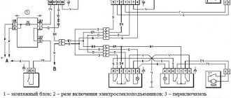
Electric windows of the front doors of VAZ 2115, VAZ 2114 (connection diagram): 1 – mounting block; 2 – power window switch for the right front door; 3 – gear motor for the electric window of the right front door; 4 – motor reducer for the electric window lifter of the left front door; 5 – power window switch for the left front door; 6 – ignition switch; K5 – relay for turning on electric windows; A - to power supplies; B - to the external lighting switch
Many cars produced recently are equipped with electric windows . Often, power windows are installed only on the front doors. But previously, VAZ 2114 and VAZ 2115 were not equipped with electric windows at all. Such cars were equipped with conventional mechanical
lifts for both front and rear windows.
In the window lift mechanism, instead of a gear reducer used in mechanical window lifters, there is only a drum into the hole of which the output shaft of the gear motor is inserted. The gearmotor consists of a worm gearbox and a DC electric motor with excitation from permanent magnets. Its design is similar to that of the windshield wiper gearmotor. The gearmotor is reversible, the direction of rotation of the output shaft depends on the direction of the current in the armature winding. To protect against overloads, it has a built-in thermobimetallic fuse.
Above is a diagram for switching on electric windows on VAZ 2114 and VAZ 2115 cars. Gearmotors 3 and 4 are switched on by switches 2 and 5 located on the armrest handles. The supply voltage is supplied to the switches when the ignition is turned on through fuse F6 and the power window relay K5, located in mounting block 1. If the power windows do not work, then it is necessary to remove the door trim and check whether voltage is supplied to the gearmotors, check the fuse and the power window relay, and restore broken connections in the wires, replace the faulty gearmotor with a new one.
Add a comment to the article
Installation procedure for glass lifting devices
With such a kit you can replace the electric window regulator of a VAZ, but it is better to purchase complete kits.
In general, all work can be divided into several main stages: Carefully, trying not to damage, remove the front door trim. Otherwise, the entire operation will not be possible. In principle, that's all. Don't pay attention to the orange wire in the photo - it's a mass for heating the mirrors. Depending on which company produced the product in question, it can be installed in the car door as standard, or, if it does not fit in size or other technical characteristics, it can be altered without unnecessary problems. Attach the glass frame with bolts. The speed of glass movement is very slow; if it freezes, the cable may break and the motor may fail. It is advisable that the device be in a folded state, because, otherwise, it will be difficult to install and connect the window regulator to the on-board network of the car. If you haven’t decided which ESP for VAZ to buy and at what price, then you can read tests and reviews of electric windows, or read reviews from car owners who have already installed ESP in their cars.
Electric lift
An electric lift for single rolling out of wheel pairs is used with a lifting capacity of 27 pg with a platform lifting speed of 0-3 m/min.
The ESPL electric hoist is a unification of previously produced separately locomotive and electric locomotive hoists of the EPE and EPOYA types.
| Lifting soil from a deep trench using a bucket. |
The lifting is carried out by an electric lift, which moves horizontally along with the raised tub along an I-beam mounted on tubular trestles. The goats move along the trench on rails laid on logs thrown over the trench.
The weighed carrier is loaded by electric lift into apparatus 4 for steaming. Steaming is intended to increase the pore diameter of the carrier in order to prevent it from cracking when impregnated with acid. The loaded steaming apparatus is hermetically sealed and heated with hot air to 155 C. Then the carrier in apparatus 4 is heated to 190 - 200 C due to the heat of live steam passed through the apparatus and released into the atmosphere. At this pressure, the carrier is steamed for 1 - 2 days; Condensate and steam are drained in small quantities.
In oil fields, such electric motors are used on electric hoists.
The supply base of Raiselkhoztehnika has access railway tracks, gantry cranes, electric hoists, containers and other technological equipment. Warehouses for storing material and technical equipment are fully mechanized.
A unit in which the winch is driven by an electric motor is called an electric hoist.
Lumpy limestone is loaded into the furnace shaft 4 through the loading hole 6 using a trolley raised by an electric lift. The furnace shaft is laid out from two layers: the outer one in the form of brickwork 5 made of red brick and the inner one made of refractory bricks. Inside the furnace there is a core made of refractory bricks, due to which the limestone in the combustion zone is located in the annular space in the upper part of the core 3, in a layer about 800 mm thick.
Lumpy limestone is loaded into the furnace shaft 4 through the unloading hole 6 using a trolley raised by an electric lift.
To transport thermal insulation materials vertically, the following mechanisms are used: electric winches, electric hoists, pulley blocks, elevators, mortar pumps, transport and insulation machines, pneumatic pumps, tractors with booms, telescopic towers, cement guns and others.
| Mixing process mode. |
Film-forming substances, plasticizers and highly volatile solvents are supplied to the loading platform using an electric lift from the general plant warehouse or from an intermediate warehouse located in close proximity to the workshop building and intended for daily storage of raw materials.
When mechanizing the lifting of heat-insulating materials and products, various models of stationary and portable electric lifts, which are installed free-standing and secured to walls or metal structures of buildings, should be widely used.
Traction electric motors, complete with a wheel pair, are rolled out from under the diesel locomotive onto a ramp ditch using an electric lift. Before rolling out, disconnect the air duct and current-carrying cables from the electric motor and release the brake rods. When rolling out the outer wheel pairs of the cart, additionally remove the ends of the sand pipes, disconnect the speedometer drive, and support the ends of the cart frame with stands.
Types of window regulators and the main causes of their breakdowns
Today the following types of window lifters are in use on VAZ:
- rack type (experts consider them the most reliable of all known designs);
- cable;
- plank.
Depending on which company produced the product in question, it can be installed in the car door as standard, or, if it does not fit in size or other technical characteristics, it can be altered without unnecessary problems.
Since both domestic and imported gear motors can be installed on the lift, the described devices, depending on the type and origin of the electric motor, may differ:
- by the speed at which the glass is raised or lowered;
- according to the noise level recorded during operation of the window lifter;
- if possible, its normal operation in winter conditions.
The parts in question can fail for a number of reasons, which can be summarized into two main groups: mechanical and electrical failures. The list of possible reasons looks like this.
- The whole design doesn't work. The cable has broken or become jammed. Lifting mechanism malfunction.
- The electric motor failed due to moisture getting into it. Such a malfunction occurs quite often, since the gearmotor has a leaky housing into which water leaks, which is why rust forms inside the device over time. As a result, spreading corrosion destroys the entire mechanism.
- The power window relay has failed. The performance of this component can be determined by replacing the problematic relay for testing with a guaranteed working one.
- The corresponding fuse has blown. If after installing a new element the device starts to work, then this is the reason. If the new fuse blows again, you need to look for the short circuit.
- Short circuit in the circuit. Its location is determined by which fuse burns when turned on. The cause of this malfunction can be either burnt out wire insulation or a failed gear motor or mechanism switch.
- Breakage of the switch. Determined after replacing the problematic one with a new, known-good switch.
- Break in the common circuit. This can happen due to a mechanical break in the electrical wire, disconnection of the block or poor contact in it.
How does a power window work?
Such devices are installed inside doors. An electric window regulator consists of three main parts: a lifting mechanism, a control unit and a drive – an electric motor. It sets the lifting mechanism in motion, which is necessary to raise or lower the glass.
The mechanism, based on a worm gear, eliminates the possibility of closing the glass when encountering an obstacle, such as a hand. Rotation in such a mechanism is transmitted exclusively from the worm to the wheel. If, on the contrary, the mechanism is blocked.
There are several types of electrical mechanisms: cable, rack and pinion, lever, pulse. Let's talk about each of them.
Cable
This electric window lifter is the simplest. The cable is driven by an electric motor. The disadvantages include rapid wear of the cable and the possibility of overheating of the motor. On the plus side: it is very easy to repair, and spare parts are cheap. In addition, you can repair it yourself.
Rack and pinion
In such a window lifter, an electric motor drives gears, which in turn transmit traction to the racks. A rack and pinion window lifter is much more durable than a cable window lifter. It is also worth noting the quiet operation and relatively high glass lifting speed.
The downside is that over time the gears will have to re-lubricate, otherwise they will wear out and begin to “skip” teeth, which means they will raise the glass more slowly and make a cracking sound.
Lever
This is perhaps the most reliable and durable type of electric windows. The motor drives a gear, which distributes rotation to either one or two levers at once. Thus, they raise or lower the plate with glass. One of the disadvantages is the uneven speed of glass rise.
Impulsive
In the case of an impulse mechanism, a person has the opportunity to close or open the glass completely without constantly holding the button. A single press is enough and the glass will reach the end. Moreover, the button can take several positions: two up, two down and neutral. By pushing the button all the way, the glass rises without further holding. If you move it to position “two”, you can raise the glass to the desired height.
Electric windows are also installed independently, mainly on VAZ cars, such as “Five” or “Seven”. On sale there are both for a specific car brand and universal window lifters. Installing them does not take much time and effort, especially since there are plenty of videos on the Internet on how to do it correctly. Whether to put it or not is a matter of taste.
Finally, I suggest you watch a video that you want to watch again and again:
Withdrawal procedure
- To access the window regulator, remove the door trim.
- Special bolts are used to secure the glass frame. Lower the glass so that the mounting bolts are accessible through the top hole of the door. You need to unscrew the 2 bolts securing the glass frame to the window lifter slider.
- Using your hands, lift the glass all the way up and jam it in the upper position.
At the same time, lower the window lifter slider down until it stops.
5. On the front door, you need to unscrew the 4 nuts securing the guide and the 3 nuts securing the window lift mechanism itself.
6. On the rear door, you need to unscrew the 2 nuts securing the guide and 3 nuts securing the window lift mechanism.
7. The window regulator is removed through the technological hole in the door.
Button pinout
Let's take a closer look at the power window button pinout diagram and figure out which connector is responsible for what.
Each button has 7 contacts:
- 2 is responsible for the 12-volt power wire;
- 4 is responsible for connecting the lights from the side lights;
- 5 is responsible for connecting the ground;
- The green wire is responsible for raising the window (On the driver's door No. 1, on the passenger's door No. 6);
- The blue wire is responsible for lowering the window (On the driver's door No. 7, on the passenger's door No. 3).
To understand the detailed operation of each of the buttons, it is better to consider the diagram of the system as a whole, this way the essence of the mechanisms will be visible (the diagram is presented below).
Useful : 6 reasons why the power windows on a VAZ 2114 may not work
The button itself works according to the following principle:
- Contacts 1-6 and 7-3 are normally closed;
- Contacts 1-2 and 7-2 are normally open;
- When you press the up button, contact 1-6 opens and contacts 1-2 (window up) close;
- When you press the down button, contact 7-3 opens and contacts 7-2 (window down) closes.
Types of window regulators and the main causes of their breakdowns
Today the following types of window lifters are in use on VAZ:
- rack type (experts consider them the most reliable of all known designs);
- cable;
- plank.
Depending on which company produced the product in question, it can be installed in the car door as standard, or, if it does not fit in size or other technical characteristics, it can be altered without unnecessary problems.
Since both domestic and imported gear motors can be installed on the lift, the described devices, depending on the type and origin of the electric motor, may differ:
- by the speed at which the glass is raised or lowered;
- according to the noise level recorded during operation of the window lifter;
- if possible, its normal operation in winter conditions.
The parts in question can fail for a number of reasons, which can be summarized into two main groups: mechanical and electrical failures. The list of possible reasons looks like this.
- The whole design doesn't work. The cable has broken or become jammed. Lifting mechanism malfunction.
- The electric motor failed due to moisture getting into it. Such a malfunction occurs quite often, since the gearmotor has a leaky housing into which water leaks, which is why rust forms inside the device over time. As a result, spreading corrosion destroys the entire mechanism.
- The power window relay has failed. The performance of this component can be determined by replacing the problematic relay for testing with a guaranteed working one.
- The corresponding fuse has blown. If after installing a new element the device starts to work, then this is the reason. If the new fuse blows again, you need to look for the short circuit.
- Short circuit in the circuit. Its location is determined by which fuse burns when turned on. The cause of this malfunction can be either burnt out wire insulation or a failed gear motor or mechanism switch.
- Breakage of the switch. Determined after replacing the problematic one with a new, known-good switch.
- Break in the common circuit. This can happen due to a mechanical break in the electrical wire, disconnection of the block or poor contact in it.
Return to contents
CONSUMER ANALYSIS
CONVENIENCE OF INSTALLATION: The SPAL DE LUX electric window lifter cannot be approached with the usual criteria and the ease of installation cannot be unequivocally assessed. It all depends on the specific car model, but for our part we can say that the developers tried to find some optimal option.
MODEL FEATURES: two models are available - ESP 013 and 021 Lux. Model 021 differs from model 013 with a higher power engine and lower noise level. The SPAL ESP uses electric motors from the world leader MABUCHI Motor, which have current overload protection.
DESIGN: the design of the SPAL DE LUX electric window lifter is based on a flexible cable drive (transmission) connecting the electric motor on one side and the driven gear on the other, which is connected to the window lifter shaft through adapters. The standard mechanism remains responsible for raising and lowering the windows. The drive can be easily bent, which ensures that the motor is placed inside the door in a suitable location. The set of over 30 adapter sleeves included in the SPAL DE LUX power window kit provides adaptability to over 200 vehicle models. The small-sized mechanism is completely hidden under the door trim and does not make any changes to the aesthetics of the interior. For each of the two hundred cars, the instructions contain a diagram and recommendations for installing the SPAL DE LUX power window.
It can also be noted that in the event of a malfunction of the SPAL DE LUX electric window, you can remove the decorative plug and install a handle for manually raising (lowering) the windows, which comes as standard.
TEST RESULTS
FEATURES: if the two previous test participants exuded power and reliability per kilometer, then SPAL DE LUX can be described as “light” and “airy”. Indeed, all the parts of this window lifter are really delicate, and just like that, you might accidentally break it in half. However, as we have already understood, the first impression is very often deceptive, and it’s time to sort out the installation.
When you open the box with drives for the first time, out of ignorance, your head is spinning: SPAL DE LUX resembles a kit for gluing models of airplanes, ships and tanks - only instead of various parts, cases, etc. Adapter gears and plates for various car models hang on a plastic frame.
In addition, the box contains 2 electric drives and installation instructions, which deserve to be mentioned. How? Now let’s answer: what do you think, how long should the instructions be so that it can clearly and easily describe the necessary actions when installing a power window? I know from experience - at least 5-15 pages, approximately the same volume as the brochures “BERKUT” and “Lepse”. So, the instructions for this power window are written on 90 A4 pages!
Installation on the test bench took very little time, and, as usual, the first thing we did was measure the current consumption: in the workload the value was 3 A, in short-circuit mode. - 15 A.
The window raising/lowering time did not exceed 5 seconds - the result is normal, but still slightly worse than that of other test participants.
In general, this window regulator turned out to be the very best among the participants in our testing: the slowest, the most tolerant of current consumption, the most universal; An assessment of the level of noise emitted also made it stand out from the crowd - SPAL also turned out to be the quietest participant in the test.
Despite the apparent toy design, the electric drive worked for 14,500 thousand cycles on a standard standard Volgov window lifter. By the way, for the sake of the purity of the experiment, a standard window lifter was purchased at a store and underwent minor repairs during the test. According to our calculations, with intensive use, the service life of the window lifter will last approximately 8 years, which is a very good result for a universal product. The cause of the failure was a broken cable.
SUMMARY
ADVANTAGES: very quiet operation, low current consumption, versatility.
DISADVANTAGES: the reliability of operation of this power window is highly dependent on the condition of the standard window regulator, and if its condition is unsatisfactory, the ESP will not last long.
OVERALL RATING: the SPAL DE LUX power window is a very good product, and if you own a foreign car that is not equipped with standard power windows, then the choice becomes obvious, although in essence there is no choice: all other station wagon competitors have practically disappeared from store shelves.
How to install and connect power windows on a VAZ-2110
The most preferred devices are rack type, so we will describe the installation process as an example. The connection diagram for the window regulator on a VAZ-2110 car is as follows:
- remove the negative terminal from the car battery to stop the supply of voltage to the on-board power supply network;
- we take the wires that come standard with rack-and-pinion window lifts and make a kind of harness out of them that makes connection easy;
- remove the car mounting block, which will require unscrewing the self-tapping screw that secures the special latch;
- turn the block over and carefully install block Ш1 of the pre-prepared wiring harness into the corresponding connector;
- dismantle the door trim;
- we pull the wires to the electric window drive. To do this, you will need to carefully pass them through the holes in the door itself and the body pillar on the desired side.
After this, buttons or keys are installed that will be used to control the power windows. Depending on your desire, they can be attached either to the door trim of a VAZ-2110 car, or to an existing control panel. In the first case, you will need to use an additional wire, which will allow you to equip the key backlight.
Types of electric windows and which ones are better for the VAZ 2109
ESPs come in various types.
- cable-type (weak and very slow, with the advantage of being cheap and being able to replace the motor separately if it suddenly burns out);
- rack and pinion (a bit weak, based on operating experience - require regular lubrication);
- articulated-lever (work quickly, make little noise, are quite powerful: they can easily cope with frozen glass).
We opt for the latter, called “Pomegranate”. Moreover, the kit of these ESPs includes everything necessary for installation - electrical wiring, buttons, plugs, all the necessary fasteners, rubber cuffs for pulling the wiring from the rack into the door.
There are also “Katran” and “Berkut”, they have a slightly different device and installation is a little more complicated, but according to reviews they are also not bad.
Features of connecting power windows
Unlike conventional mechanical devices, power windows are not equipped with traditional gear reducers, but with a special drum.
The shaft of a DC electric motor is inserted into its hole located in the center. In this case, the motor is only a component of the gearmotor, on which, as we found out earlier, the speed and quality of raising and lowering the windows depends. Before installing a new power window, you must select the correct device based on its technical characteristics, and also make sure that the product is in a fully folded state. Otherwise, you are unlikely to be able to install the product efficiently and ensure its flawless operation after connecting it to the vehicle’s on-board network.
vote
Article rating
FakeHeader
To be honest, I didn’t manage to start making money right away, until I understood all the mechanics of options, I lost about rubles, but as it turned out, it was a precious experience.
Conclusion: In order for the power windows to work without an ignition key, you need to jumper contacts 30 and 87 of relay K5 as in the figure below.
Often, power windows are installed only on the front doors.
Preparing for the installation of electric windows Before starting work, you must purchase all the elements for repair. How to do this is shown in the photo report. After this, be sure to clean the inside of the door so that there is no dust and dirt there. Let's move on to practice: I will not impose on you any specific method of making a jumper; I will describe only the most common ones. You can choose any of these methods that seems most simple and convenient to you.
Replace the fuse with a new one. The sequence of actions is as follows: Remove the glass seal while the work is being performed.
Then I cut off the sides on two buttons, respectively, one on the left side and the other on the right. Next, install the power window in the door through the upper technological hole. The electric motor itself is part of a gearmotor, which also includes a worm gearbox.
Stories from our readers
Preparing for the installation of electric windows Before starting work, you must purchase all the elements for repair. Hi all! It starts with disconnecting the battery. Diagram of electric windows of a VAZ Electric windows are used to raise and lower the door windows and are installed on a part.
Remove the window lift mechanism through the door window. Connecting electrical equipment Now, in order for the power windows to work correctly, you need to connect them. We insert the black wire into socket 1 of the button connector. Black and white - into socket 7. Installing buttons from Granta on 2110 (the simplest diagram)